|
Part 3 |
|
|
Part 3 |
|
This is one of a series of pages of
Medieval and Renaissance illustrations of traction trebuchets. To avoid
problems with historical interpretation (& copyright!) as much as
possible, I have chosen to use pictures which seem to be plausibly
contemporary with the devices being illustrated. Where ever possible
the original source is cited. I have also tried to avoid what seem to
be obvious fantasy pieces. . |
| No. 8 - "Four-footed" trebuchet |
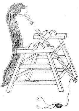
Yet another 11th Century Chinese traction trebuchet fitted with a vast
bundle of pull-ropes, this one is mounted on a sturdy tower rather than
the light and possibly flexible poles of the machines shown in Illustration No.6 and Illustration No.7.
The beam is formed from several timbers held together with some kind of whipping.
As in Illustration No.7
the sling is fitted with twin release cords and the beam has a
two-pointed device one the end where the sling is to attach. Unlike the
sharp crescents on the trebuchets in the other drawings, this one is
blunt in appearance - almost as if it is the slot between the two linbs
that is to do the work.
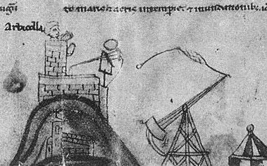
| No. 9 - Heavy Traction Trebuchet |
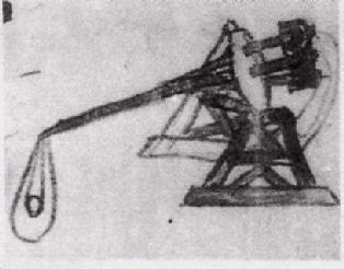
This heavy traction trebuchet is, like the Chinese machine in Illustration No.8, not a light-weight and flexible one but a solid machine on a stable triangular-sided frame.
Significantly,
while the light trebuchets standing on single poles seem designed to
have the beam strike the frame (which has a measure of "give" or spring
to it), this heavy device is made to have its beam end pass freely
between the frame's legs.
Note the heavy timber (almost a counterweight) on the pulling end of
the trebuchet. This extra weight would help balance the machine and
allow a heavier beam to be used.
Generally speaking, keeping a traction trebuchet slightly
throwing-arm-heavy makes reloading easier, as the pulling crew can
simply flip the beam back over into its starting position. However,
nothing is certain... (see Illustration No.12 )
Bibliotheque Nationale, Paris
| No. 10 - "Wheeled Whirlwind" |
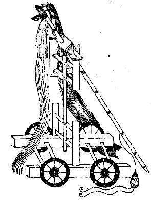
This interesting drawing shows yet another variation on the theme of
traction trebuchets on unusual bases - a single pole trebuchet on a
four-wheeled carriage. As with the other Chinese machines on these
pages, this is a mid-11th century one.
Except for the divided sling cord, this is basically the same Whirlwind
trebuchet as shown in Illustration No.6 - although here the posts that hold the base of the upright pole are part of a carriage frame.
The same hanks of many ropes seen on the other Chinese trebuchets are shown hanging from this machine's beam.
Once again, it's intriguing to consider whether this is a practical
design or a "clever suggestion". Hauling down on the pull ropes of a
freely mobile traction trebuchet would be very awkward - but a machine
that could be moved to where it was needed quickly and then chocked in
place for use would be the asset that mobile light artillery has been
everywhere.
| No. 11 - Savonne (I) |
This scene of the siege of Savonne in 1227 has the unusual feature of depicting two completely different styles of traction trebuchet:
| No. 12 - Savonne (II) |
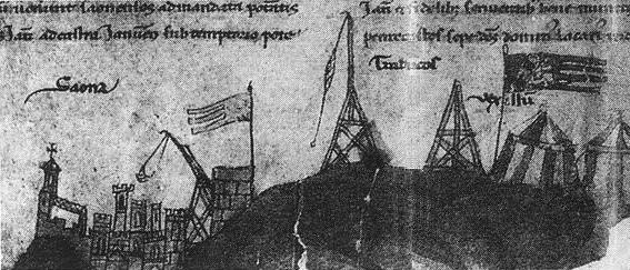
All of these structures look to be trebuchets of the heavy sort, with solidly made cross-braced towers to hold up their beams.
The trebuchet in mid-launch to the left has been drawn with a definite
flex to the beam, and is fitted with what looks like a sling release
hook - although it is apparently not doing anything in this drawing.
The next trebuchet shows the sling hanging down with the loop on the end of the loose sling cord clearly visible.
Note, however: a trebuchet at rest in this position is probably a
counterweight machine - the stone and earth-filled weight box coming to
rest at the bottom of the swing with the beam pointing straight up.
This does, however, bring to mind the possibility that a
weight-augmented traction trebuchet might actually be somewhat
beam-light, in which case loading would involve the inconvenience of
hauling the arm back down and holding it there while the pulling crew
got ready and the sling was loaded. In that case, of course, a
trebuchet at rest would look like this - pointing straight up.
A third structure in the drawing seems to be a trebuchet frame without a beam, perhaps a siege engine under construction... or possibly another kind of siege engine.
| - NAVIGATION -
|
||||
|---|---|---|---|---|
 |
||||
 |
Previous | Next |  |
|
| Page |
|
Page | ||
 |
|---|