|
Part 2 |

|
Part 2 |
|
This is one of a series of pages of
Medieval and Renaissance illustrations of traction trebuchets. To avoid
problems with historical interpretation (& copyright!) as much as
possible, I have chosen to use pictures which seem to be plausibly
contemporary with the devices being illustrated. Where ever possible
the original source is cited. I have also tried to avoid what seem to
be obvious fantasy pieces. . |
| No. 4 - Maciejowsky Bible (I) |
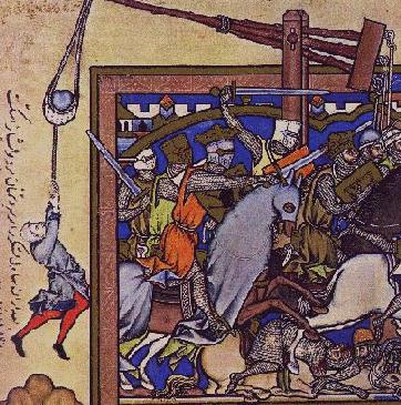
The drawing is much used in books on siegecraft, and has also been
interpreted as a weight-powered machine whose counterweight is in the
form of rocks (out of sight) hanging on the ends of the ropes.
While this is certainly possible (cf the odd Counterweight Illustration No.19),
the simple traction trebuchet interpretation is the one Occam's Razor
favours - and everything in the picture is consistent with it.
(The style of illustration in the Maciejowsky Bible uses the technique
of representing extra troops etc by showing their weapons appearing
above the heads of the forground figures. The lack of pulling crew here
can be seen to be no harder to accept than the numerous "unmanned"
cleavers and spears in other scenes.)
Note the rope attachment on this machine's beam end. The rope to ring
to eye-bolt connection means that the repeated rubbing movements are
taken as a metal-to-metal contact. Grey Co experience has found that
this is very useful and protects the pull ropes, which otherwise wear
through quickly.
The artist has made a particular point of showing the crew member
hanging on to the sling, the provision of a rope handle to do so - and
has drawn attention to his having been lifted off the ground (shown
some distance beneath him) by the trebuchet.
Of course, if we wanted to be difficult we could consider this to be someone loading
a counterweight trebuchet, hauling the beam down by a sling cord...
except that here the sling cords are already hooked onto the release
prong and the projectile is loaded.
| No. 5 - Maciejowsky Bible (II) |
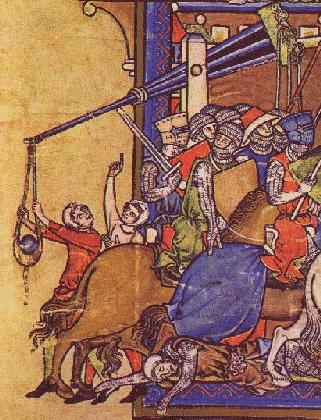
Both Illustration 4
and Illustration 5 show the machines in unusual perspective. The
fanning-out beams at the pulling end of the main beam appear to be
arranged vertically. This is a very interesting and difficult point
since a traction trebuchet can (and possibly did) work in either a
vertical or horizontal arrangement of rope attachments.
To get a hint as to how the machine is supposed to be in this case we
can look to other features of the illustraions. In this and other
drawings in the Maciejowsky bible crossbows are shown rotated in the
same way. Since crossbows are not likely to have been used turned
sideways (the quarrel or bolt would fall out for a start), the
conclusion is that the artist or artists are drawing things rotated to
show how they work. For the trebuchet, it implies that the rope-holding
triangles are actually forming a horizontal fan.
| No. 6 - Hsuan Feng (Whirlwind) |
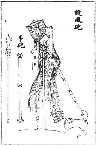
Here we have a Hsuan Feng (Whirlwind) trebuchet from China (c.1044).
It is another single pole machine like the one shown in Illustration No.2. This one is fitted with the familiar sling, a loop visible on the end of the free sling cord.
Note the huge number of pull-ropes. The implication is that a crew-member goes onto the end of each one.
In middle-eastern poetic descriptions this bundle of trebuchet
pull-ropes is referred to in terms that involve images such as "witches
hair". This drawing shows it well.
Why Chinese trebuchets in this collection of otherwise European
medieval weapons? The evidence is that the traction trebuchet was
invented in the far east and made its way westwards across the Eurasian
continent to finally reach Europe. Whenever this happened, the traction
trebuchet was in the Middle East by the 6th Century.
| No. 7 - A battery of Hsuan Feng (c.1044) |
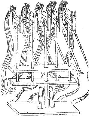
The sling design on this machine (and Illustration No.8 & Illustration No.9) is radically different from that of Illustration No.6
and the European designs. The free end of the sling is held by two
separate ropes which look like they each have their own attachment
prongs on the beam-end.
Although the drawings in Illustration 8 & Illustration No.10 could be interpreted as showing a "Maciejowsky-style" hold-down rope, this drawing is clearly of twin support ropes.
What purpose would this double arrangement of free sling cords serve?
Grey Co experiments have shown that large and bulky sling pouches
necessary to hold large or loose bundles of projectiles tend to develop
a pocket in the free end which fouls the projectiles as they leave
during launch. Possibly the double release created a much more open
sling - and while the sling was closed it would hold its load between
three suspension points.
Note the "crescent moon" object on each beam's end. This could well be
a double release prong - one sling cord loop for each "horn" of the
crescent.
| - NAVIGATION -
|
||||
|---|---|---|---|---|
 |
||||
 |
Previous | Next |  |
|
| Page |
|
Page | ||
 |
|---|