|
Spotters Page |
|
|
Spotters Page |
|
|
Traction Trebuchet? |
A trebuchet is a missile-throwing machine where a long pivotted beam, much longer on one side, has the short side pulled down causing the long side to rise quickly. A sling attached to the end of the long side of the beam whips over, releases itself and hurls the projectile it held.
On a "Counter-weight" Trebuchet the power used to pull the short end of the beam down is gravity - because the trebuchet builders hang an enormous weight (such as a large box full of stones and earth) on it
With a Traction Trebuchet the power is human muscle. A team of people
haul down on ropes hanging from the short end of the beam. This bundle of ropes
is what poetically-inclined Eastern writers have compared to a witch's
hair.
A handy feature of a traction trebuchet is that, while a counter-weight
machine has to have its weighted beam slowly winched back into the start
position, the pulling crew of the people-power machine can just pull on their
ropes again and make the beam fall back into place.
Let's have a look at the parts of a traction trebuchet...
|
Traction Trebuchet |
| The
Beam-end & Ropes This is how the crew (seen below) get to haul down on the beam. The short end of the beam usually has a kind of rake-like spreader to which the hauling ropes are attached. The extra width of this "hay-rake" gives the crew a bit more room to work. Even so, on a large crew a few elbows and ears must accidentally meet... |
The
Axle and Support For the crew to be able to make the beam swing around above their heads, the axle has to be supported high above the ground even on a small machine. In this case the wooden axle is held by a square frame that is mounted on the top of a single pole. In other machines two large posts - one each side and rising all the way from the ground - hold up the axle and beam |
The
Sling Release A trebuchet is not just a lop-sided seesaw - the sling adds a huge amount of extra whip to the shot and can double the range obtained. The way the sling works is simplicity itself - the pouch holds the stone projectile as long as both cords are connected to the beam end... and one of the sling cords is designed to fall off during launch. (see the loop and hook?) |
|||
 |
|||||
| The
Hauling Crew These soldiers are the power of the machine. They must all haul down on those ropes above their heads at the same moment, causing their end of the beam to suddenly drop and the much longer other end of the beam to rise and whip over. |
Protection The trebuchet and its crew are close to the enemy - perhaps only 100-200 metres away ... and that's within bow-range. If they are lucky they might have wooden or hide-covered defenses to protect them. If not, they'll just have to hope that "covering fire" from their own archers will put the defenders off their aim. |
The
Sling Handler This crewman has to re-hook and load the sling pouch after each shot. Assisting him will be another crew bringing up new stones to feed the trebuchet. Another part of his job is to hold onto the sling during launch. This helps make the crew's efforts more synchronised and, by changing the angle he holds the sling, he can aim the shot a little. |
|||
|
Different Shapes and Kinds |
| The "Tower" type
This shape, which looks a little like a modern oil-drilling rig or
windmill stand, was probably the first to be used in Europe. This design allows the crew (who stand inside the structure) to approach the target closely with considerable protection. If the besieged townspeople had their own artillery, a fire bomb thrown from their trebuchet could destroy a plain wooden machine. If this was likely to happen a fireproof coating of the sort illustrated would have to be made. |
| The Single Pole type
An elegant-looking design, this one is light, portable
and lacking in any in-built protection. These machines turn up in drawings of around the late 12th Century in Europe (although they appear in Chinese illustrations much earlier). |
| The Two-Post type
This sort of machine - apparently tougher and cruder - appears in Western Europe and looks to be the sort shown on the Carcassonne cathedral and may be the type shown in the mid-13th Century Maciejowski Bible. In this design the beam can pass between the uprights of the frame and, rather than an impact, it is the crew's ropes that stop the beam after the rock is thrown. I have left the base largely undrawn in this sketch, as the base is not shown well on the originals. Grey Co experiments have found that sideways bracing timbers, in addition to the backward facing ones shown, make the machine much less "wobbly" and more consistent in its aim. |
| The Heavy type
This is just a heavier (and probably larger) version of the two-pole machine, its support posts being replaced by a sturdy tower. In this it is almost a return to the old tower style - although much more heavily constructed. Here also the beam can pass between the legs of the support and
stopping the beam is up to the crew and their ropes. This sketch is based on the machine shown here. |
|
"Rake" or "Axe" |
| Although I have chosen to show only horizontally arranged
rope attachment triangles on the drawings in this page (what I have called
the "rake" arrangement), a traction trebuchet can work with the triangle
turned to a vertical arrangement. Here we look at the two orientations and
recognise that some medieval drawings can suggest one or the other way -
or leave the viewer mystified as to how it was supposed to go. |
|
|
|
Advantages:
|
Advantages:
|
Disadvantages:
|
Disadvantages:
|
|
|
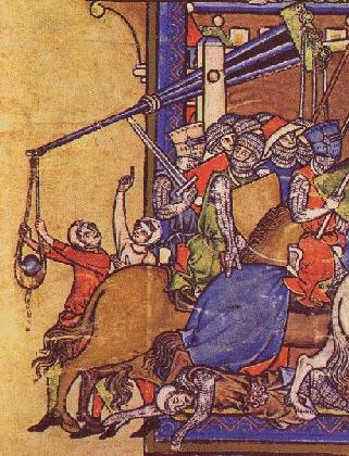
| How many of the bits that you've just read about can you
see on this picture from the marvelous 13th Century Maciejowski Bible?
Remember how the sling handler would hold the sling during launch? Well, in this drawing you can see a rope handle provided for this purpose. |

|
Grey Company Trebuchet Page |