|
The Treb Files
Part 4:
|
|
|
The Treb Files
Part 4:
|
|
|
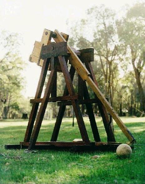
| Name: | Magog |
| AKA: | The Sokil Machine, Sokil, Number Two |
| Class: | Hinged Counterweight Trebuchet |
| Size: | Throwing arm 2.10m, axle height 1.6m |
| Power Unit: | 100 kg - 200 kg of scrap iron and bags of sand in a heavy iron-strapped wooden bucket. |
| Projectiles: | 1kg iron balls as standard, plus plastic bottles, basket balls, 1-2kg rocks, iron-headed darts, trouserballs, flour bags... |
| Range: | approx 100m with 1 kg iron balls. |
| Based upon: | The frame was also inspired by a Traction treb illustration (Bibliotheque Nationale, Paris ) and made for ease of disassembly. |
| Status: | in active use. |
|
Built in time to be completed AND tested well
before the 1997 Australian Medieval Conference, Magog's ability to be
pulled apart and packed away into a small part of a trailer was
invaluable as it was carted behind a mini-bus across the Australian
continent to be demonstrated in front of fellow re-enactors. This trip might well be some kind of a record - Perth, Western Australia to Geelong, Victoria is a journey comparable to, say, California to Florida ...or from Belgium to Greece. |
 |
|
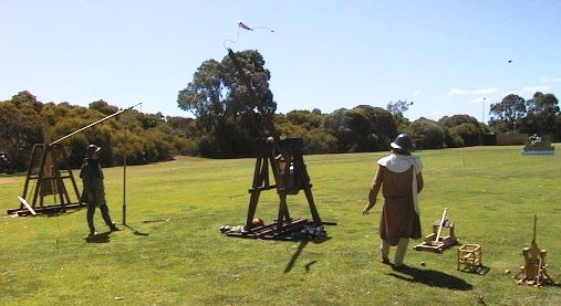
Magog sits ready for action at our usual firing range - a friend's farm a little over half an hour out of town.... Only one item in this photo is "theatrical" and not for serious hurling use. Can you pick it? Answer: The stone ball in the foreground is actually sand-coated polystyrene foam - useful for "static" displays or where you don't want even a hint of serious weaponry to be present. |
| |
|
|
|
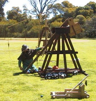
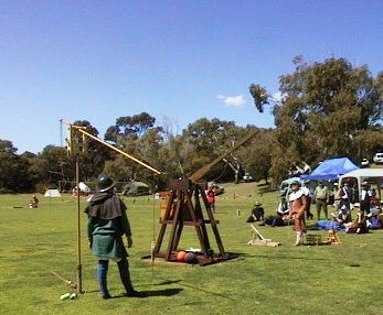
Here
John (aka The Worm) begins the loading of Magog. The beam has been
hauled down and the trigger fitted to the steel loop on the underside
of the beam. The trigger is secured in place to prevent an accidental
launch by tying it to the beam with the firing lanyard. The next step, which John is shown doing, is to fold the sling and fit its release ring to the prong on the end of the beam. After that the projectile is placed in the sling pouch and laid in the launch trough. |
|
| |
 |
|
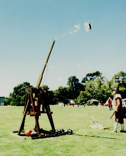
Surrounded by other Grey Co siege engines and models, Magog cranks out a "trouserball". These odd projectiles (which can be seen around the base of the trebuchet here and in the first photo) are an attempt at safer missiles for public performances. Their construction starts with an old pair of jeans rolled up and stuffed into one or more calico bags. These are then wrapped with tape to hold their shape in flight. The target of this shot is a wall of cardboard boxes on which we have seated "Steggle" the dummy wearing a breastplate - a sort of armoured Humpty Dumpty. |
| |
|
|
|
A
trouserball in mid-launch. The sling swings out and begins to overtake
the beam. With proper design and tuning it will not release until the
maximum amount of speed and energy has been put into the projectile. You can see that both operators are watching the machine closely as it fires - in particular you want to keep the projectile in sight... |
|
|
|
|
|
|
|
|
|
|
Watch
out! A trouserball, its tape bindings broken by an earlier launch,
deforms as it experiences the acceleration in the sling and falls out. This shot went straight up (well, up and slightly backwards). Although very rare, shots like this are why we wear helmets and "keep our eyes on the ball". |
|
| |
|
|
|
|
|
|
|
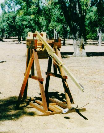
As
a crude alternative to using a sling, oddly-shaped (or just
inconvenient) projectiles can be simply attached to a trebuchet's
release prong by a strong cord which has a loop tied in the end. We tend not to use this system very often, but for some things it's the best way to go. This photo shows the trigger design clearly - and you can also see the "haul down" rope tied to the beam. This makes the first part of pulling the beam down very much easier. |
|
| |
|
|
|
|
|
|
|
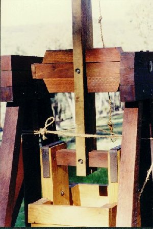
The
construction of Magog's beam is partly shown here. The section that
holds the main axle and the weight bucket axle is made from two timbers
bolted together which "sandwich" the wooden axles. The throwing end of
the beam is a single length of timber that is also bolted into place in
a cut-away at the other end of the two. (See the "portrait" of Magog at the top of this page for more details of the beam's construction.) The heavy wooden bucket can also be seen. Forged iron straps approximately 4mm thick run down the sides and pass underneath, supporting the bucket base. (The rope seen passing around the base timbers and the beam is a safety measure to prevent unauthorised (usually small) people from swinging the bucket and injuring themselves - or our trebuchet!) |
|
| |
| Photos by David Barron, Kate Miners and Richard Stein. |
| Last Edited: November 2000 |
|
© Russell Miners 2000. |