|
Part 3 |
|
|
Part 3 |
|
This is one of a series of pages of
Medieval and Renaissance illustrations of trebuchets. To avoid problems
with historical interpretation (& copyright!) as much as possible,
I have chosen to use pictures which seem to be plausibly contemporary
with the devices being illustrated. I have also tried to avoid what
seem to be obvious fantasy pieces. . |
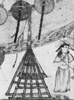
| No. 9 - Siege of Jerusalem |
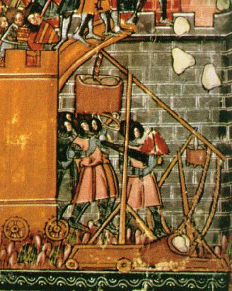 It shows two trebuchets in use next to a wheeled siege tower. The trebs
are fairly basically drawn, but show the main features - a box of
rocks, a sling containing the projectile, bracing timbers on the
uprights and a timber base.
It shows two trebuchets in use next to a wheeled siege tower. The trebs
are fairly basically drawn, but show the main features - a box of
rocks, a sling containing the projectile, bracing timbers on the
uprights and a timber base.
There is, of course, an alternative use for wheels on trebuchets.
Many illustrations on these pages imply that trebuchets in their
operating positions were subject to enemy arrow fire and siege engine
counter-battery. If an assembled machine could be hauled into position
(perhaps with its bucket unloaded) it would not have to be built under
fire. Wheels would be one way of doing this - although giving the
machine a sledge-like base and dragging it also seems plausible. Once
in place the trebuchet need not have been left free-moving .. it might
also have been anchored or chocked.
As a final word, it seems hard to imagine how or where you would fit wheels to something like Villard de Honnecourt's base. Those side-bracing transverse timbers present quite a challenge.
| No. 10 - "Mongol" Trebuchet |
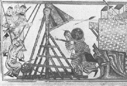 Compare this machine to the trebuchet shown in illustration No.8...
There is a winch at the rear of the machine, and the engineer is wielding a mallet, presumably to trigger the trebuchet.
Note that here too the artillery is within bowshot of the defenders.
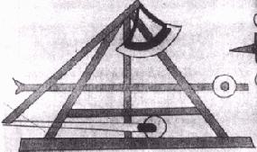
| No. 11 - "Saray album" |
Here it can be seen in the rest position, the throwing arm of its beam pointing straight up, indicating that the other beam end is much heavier. Although the base supports obscure the other end of the beam, it is very likely that this is a either a purely or partly weight-powered (rather than purely "traction") trebuchet. As no pulling ropes are to be seen connected to this short arm, we can hazrd that this is, in fact, completely weight powered.
The drawing is unusual in showing a weight/arm assembly that fans out
very widely - it's visible on both sides of the frame's timbers - and
which appears to be rigidly attached to the beam.
Though some modern reconstructions (especially the big ones) use this
system of a solid weighted beam, not many historic pictures do.
Some French historians prefer to call trebuchets with rigidly-attached weights "mangonels". This might be one, Illustration No.7 another..
Other features to note in this image are:
| No. 12 - Hasan al-Rammah |
 This simple drawing of a Middle Eastern machine shows the same shape of counterweight as the machine shown in Illustration No.11.
Note that this machine's counterweight is not rigidly attached to the end of the beam, but is instead hanging from it like most of the other trebuchets on this page.
It is interesting to ponder why the builder has gone to the trouble of
giving the weight a curved shape. The curve of the base is roughly a
circle centred on the suspension point of the weight on the beam.
Certainly this would allow the base's frame to be made lower, since no
clearance would need to be given for the corners of the weight, but
this seems hardly likely (or worth the effort). Any ideas?
| - NAVIGATION -
|
||||
|---|---|---|---|---|
 |
||||
 |
Previous | Next |  |
|
| Page |
|
Page | ||