|
Historic Trebuchet Illustrations
Part 2
|
|
This is one of a series of pages of
Medieval and Renaissance illustrations of trebuchets. To avoid problems
with historical interpretation (& copyright!) as much as possible,
I have chosen to use pictures which seem to be plausibly contemporary
with the devices being illustrated. I have also tried to avoid what
seem to be obvious fantasy pieces. .
|
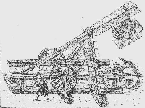
Trebuchet by Kolderer, c1507. This is obviously a later period drawing
than the Medieval ones - as the style of the artist and the dress of
the crewman he has drawn show. There are several things to note:
- This machine has been given a hugely long sling - perhaps partly to allow the artist to show the dead horse.
- The big wide wheels are here too, but drawn too small to be
realistic "get-inside " treadmills. Why the width if they are just
hand-holds? (Note: the proportions of this more modern drawing are
still strange. Would that long weight and beam end pass through a
machine this high? - No ..So the jury is still out on this one..)
- The machine is about to be triggered with a lanyard connected
to a lever mounted within the base of the engine and projecting out the
side.
- The box suspension is similar to early ones - although this time dividing into four - and supports the box from the bottom.
- The framework is fitted with rungs to climb onto the machine. (Somebody has to attach the winch rope to the beam...)
- The uprights slope inwards strongly, needing only a short axle to support the beam.
| No. 6 - Villard de Honnecourt |
|
This plan of a trebuchet base by Villard de Honnecourt (c.1250) is
allegedly the only surviving "blueprint" of any part of a trebuchet
from medieval sources. According to some there was originally more
drawn, but only this section is known.
|
|
- The winch(es) themselves are mounted off on arms to the side and
end of the machine, although the axle to which the beam is pulled is on
the end of the main trebuchet frame.
- The winch rope has a loop to engage the beam.
- Winches: is there only one? If so then a 2:1 advantage could
be being obtained, assuming that the loop of rope passes through a
pulley mounted on the beam. (no evidence for this- see Illustration No.2 and Illustration No.4)
Note that the rope is drawn as being wrapped a turn around the "top"
roller. For the one-winch arrangement to work only one end of the rope
must move past this roller - the winch end pulling back, and the
tied-off just staying still. It could be warped around the roller but
would not turn with it - ie it must slip on the roller or be on a
separate surface to the other rope end. The directions of the rope
turns illustrated don't seem to be correct to allow this to happen.
(However, this detail is not clear and, of course, even the original
drawing may not be entirely accurate.)
- Changes of direction of the winch ropes are supported by pulleys - necessary considering the loads involved.
- The base has a wide transverse member and has cross-bracing on just about everything.
|
How to Make a Trebuchet
Here are Villiard de Honnecourt's instructions that accompanied the diagram(s):
- "If you want to make the strong engine which is called a trebuchet, pay close attention here.
Here is the base as it rests on the ground.
Here in front are the two windlasses and the double rope with which one
draws back the beam ("verge") as you can see on the other page.
- There is a great weight to pull back, for the
counter-poise is very heavy, being a hopper full of earth which is two
'large toises' (roughly "two fathoms" or about 12 pieds/feet) long and
nine feet across and twelve feet deep.
("il i a une huge plainne de terre ki .II. grans toizes a de lonc et .VIIII. pies de le, et .XII. pies de parfont")
- Remember the arc of the arrow ("le fleke") when discharged and take great care, because it must be placed against the stanchion in front."
I have no idea what much of the last paragraph means - is "fleke" a
general term for a projectile? Nowhere else do we see references to
arrows and trebuchets.
Perhaps the admonition to remember the arc of the 'projectile'(?)
refers to the outward swing of the loaded sling to the rear of the
trebuchet as launch occurs. Standing behind a loosing trebuchet could
get your head knocked off..
However, "what stanchion"? ... and is the "fleke" something else that's
hazardous - a part of the trigger mechanism, the loop on the loose
sling cord...?
Note that de Honnecourt says that the windlasses are at the front of
the machine. This means that the top of the plan as shown here is the
front. Unfortunately the artist doesn't show any way for the winch rope
to pass under the axle supports and haul down on the beam. Something is
missing...
The above translation is from "War in the Middle Ages" by Philippe Contamine
| No. 7 - "Histoires d'Outremer" |
Two very basic trebuchets can be seen in this illustration from the
13th Century "Histoires d'Outremer" by ... performing a nasty piece of
unsubtle psychological warfare. For an altogether nicer image of a
trebuchet throwing a basket of something see Illustration 15
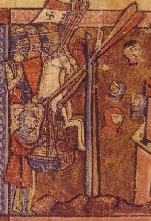
This sort of drawing of a machine looks too simple to be true -
apparently consisting of a forked branch upright supporting a beam
which is weighted with a glob of something stuck on the end.
It resembles some drawings of single-post traction trebuchets, where
the "non-throwing" beam end does not pass between two frame uprights
but instead strikes a single central one.
The proportions of the beams (short throwing arm, long weighted arm)
might be fine for lifting heavy objects, but for throwing things it is
completely the wrong way around.
(In trials with models I have
found the greatest problem with similar designs was that the weight
falls to the ground and the beam, not attached to the fork but
connected to the weight, slips forward and also crashes to the ground.
The beams impact is usually violent as it is rotating in normal
trebuchet fashion.
This lack of attachment is the major difficulty, both for this case
during launch and in stopping the beam from sliding through the fork at
any time - although nothing more complicated than the various ways
people have found to work ships' oars could work here too.)
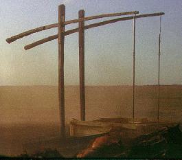
The important resemblance that this drawing bears is to a Middle-Eastern water raising device called a Shaduf (right).
Interestingly, Chinese records claim the traction trebuchet for themselves, but call the weight-powered machines "Arab" weapons.
| No. 8 - Early 14th Century trebuchet |
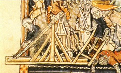
An early 14th Century trebuchet can be seen in this detail from a
dramatic little illustration (BM MS Add.10294 f. 81v) of a siege in
progress. Some features are familiar ones, but it also shows some other
aspects of trebuchet construction:
- The weight bucket has the narrow top and flared base already seen in Illustration No.1, and (to a lesser degree) in Illustration No.2.
- The launch trough is long, open ended and has a semi-circular cross section.
- The sling is very long, and this time isn't drawn as if it is held closed.
- The upright timbers are extensively braced.
- The beam appears to be "laminated" and has re-enforcing bands (perhaps rope whipping) at intervals along its length.
- NAVIGATION -
|
| |
|
 |
|
|
 |
Previous |
Next |
 |
| Page |
Main Page
|
Page |
Russell Miners
This page was last edited Jan 2000