-Home-

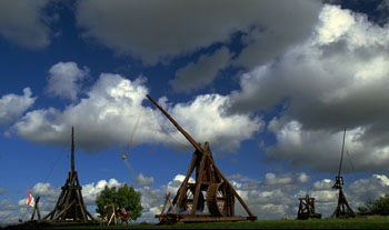
The image shows siege engines built at Middelaldercentret,
Denmark
Experimental Reconstruction
of a Medieval Trébuchet
by Dr. Peter Vemming Hansen, Nyköbing
Falster, Denmark
Acta Archaeologica vol. 63, 1992,
pp. 189 268 - Printed in Denmark all rights reserved
- Copyright ACTA ARCHAEOLOGICA ISSN OO65-OO1X
Names
- Types of Engine - Medieval
Sources - Earlier Attempts at Reconstruction
- The rules of Replica Construction
- Reconstruction of a Trébuchet
- The Base of a Trébuchet - Axles
and Bearings - The Superstructure of the
Trébuchet - Moveable Parts
- The Throwing Arm - The
Sling - The Iron Tip - Release
Mechanism - Loading the Trébuchet
- Safety Arrangements - Ammonition
- Trials - Conclusions
- References - Acknowledgements
Click
here to see an image of the 1.st trébuchet built at Middelaldercentret
in Denmark.
Introduction
We hear for the first time of leverage artillery in
Denmark in 1134. Saxo's Chronicle tells us that king Erik Emune when besieging
Haraldsborg north of Roskilde used a trebuchet. The Danes were at that
time still unskilled in the use of such contraptions, and it was Germans
living in Roskilde who built and operated the throwing machine. The type
of weapon may have been known still earlier in Scandinavia, for the monk
Abbo de St. Germain in his epic De Bello Parisiaco dated to ca. 89O, tells
in an eyewitness account that it was used at the siege of Paris by the
Vikings in 885-86 (Hoffmeyer 1958, Schneider 191O) . Another source (the
Annals of Saint Bertin, Hoffmeyer 1958) relates that the North men used
similar weapons at the siege of Angers in 873.
When and how leverage artillery first entered the
history of European warfare is not known for sure, but there is much that
points to its being an invention of great antiquity, the origin of which
is to be sought in the orient. Generally speaking there were two types
of engine a hand-operated device and one that used a heavy weight. Leverage
artillery is thought to have evolved from the simple pole sling. The hand-operated
device is thought to be the older, and both are thought to have been in
use in Europe far into the 13OO's. It is difficult to propose a finer taxonomy
as there are so many variations on a single basic principle, including
even weapons which combined the two methods of propulsion, hand power and
weight.
The German philologist Schneider ( 1910), whose primary
interest was the artillery of the Ancient world, took the view that this
was an accidental Norman invention, made late in the 900's, that later
spread to the Mediterranean area and Asia. However Schneider and another
German scholar, Rathgen (1928', have been criticized for excessive German
bias, and both of them tended to place the Germanic area at the center
of important discoveries (Hoffmeyer 1 958).
In l941 the Finnish scholar Huuri presented a study
of the Byzantine, Islamic, Indian, and Chinese sources, and succeeded in
showing that leverage artillery had been in use in Asia before it reached
Europe. In his opinion the idea originated in China, from which it spread
westsvards in the 6th century and reached the knowledge of the Arabs via
Persia and Byzantium. In the East the Japanese encountered it in the war
in Korea in 618.
Hoffmeyer in her examination of the Byzantine manuscript
of Scylitzes from the second half of 12th century (1966), described the
further spread of this weapon to the Mediterranean, where it seems possible
to follow it via Byzantium to Sicily and southern
Italy as early as the 9th century. Here the Europeans
rapidly evolved the heavy version with a counterpoise, the Frankish trebuchet,
and knowledge of this improved machine then spread back eastwards in the
ensuing centuries.
Most recently Finó has taken up the problems
around the origin of leverage artillery and come to the surprising conclusion
that the question has not been answered and it is not settled yet whether
the origin was oriental or occidental (Finó 1973).
Of course it is difficult to give a precise date
for the introduction of this new type of artillery, but the matter cannot
be viewed as categorically as Finó does, nor as definitively as
by a number of other scholars who believe they can date very precisely
when mechanical engines of war first trod into the stage of history. They
refer to a source which says that when Dionysos the Elder, ruler of the
Greek colony of Syracuse, in the year 399 B.C. was preparing a major war
against Carthage, he set up a research and development program and assembled
technicians and engineers from the lands of the Mediterranean to carry
it out. The main aim was to develop new weapons, and it seems that a mechanical
arrow-shooting device, whose means of propulsion was a large bow stronger
than a man could bend, was introduced for the first time (Marsden 1969/71,
King 1982, Soedel & Foley 1979).
A knowledge of the basic physical principles which
the various engines of war operate under has been universal knowledge among
peoples and cultures from the earliest times. Generally speaking the missile
throwers functioned in one of two ways either
using a swing arm and sling, or on the principle of the spring. The principle
of the swung sling can be seen in the primitive hand sling, which was probably
used right back in the Middle Palaeolithic cultures of Europe, Africa and
Asia, and also in the later pole sling. Undoubtedly the medieval war engines
developed from these two widely known arms. The prototype of the weapons
using spring propulsion is to be found in the bow, where there is spring
tension in both the bent bow and in the taughtened string. From this developed
the mechanical arrow-shooting devices and torsion propulsion.
Thus despite having heard about Dionysos the Elder's
war engines, we should be careful before attributing
to his technicians the whole honor of introducing these new weapons. Both
Dionysos' and later machines function according to principles that are
so simple and familiar that one and the same device could readily be imagined
appearing simultaneously at different places in the world, or types could
be used and forgotten only to be rediscovered somewhere else.
It was the economic and cultural centers that were
best able to develop and improve methods of mechanical weapon propulsion,
and naturally they also provide the best information. Both Hoffmeyer and
Huuri call attention to the task remaining in the study of the Oriental
and Mediterranean sources, and think a finer chronology will probably be
established for the development and use of the various types of weapons,
and expect their diffusion to be traceable.
After about A.D. 1200 our knowledge of leverage propulsion
artillery in Europe improves. It is frequently mentioned by Medieval authors,
and there are many illustrations in the manuscripts.
In Scandinavia there are many reports on the use
of this weapon (Alm & Hoffmeyer 1956, Sjaellands kroenike 1981), but
there are few if any medieval illustrations of it in use. In king Frederik
II's war handbook of 1578 there is a single representation of a trebuchet
(Birkelund 1988), but it is a copy and can be found in at least two other
similar versions, including the German translation of Vegetius' De Re Militari
(printed in 1529) and in Wurstisen's Basel Chronicle from the beginning
of the 1500's (Schneider 1910,. Finally the same drawing is given by Demin
(1869), who mentions having seen copies of it in other 16th century manuscripts.
The drawing dates from a time when there was much interest in the old engines
of war and ancient manuscripts were keenly studied with the object of reproducing
the various types in drawing and replica. Not least Leonardo da Vinci with
great imagination devised a multitude of mechanical devices for military
purposes.
Leverage propulsion weapons are thought to have
been in use in Europe as late as the first half of the 16th century, but
by degrees the high trajectory mortars became so efficient that the old
weapons fell out of use. According to Hoffmeyer 1958, it was
still possible in 1575 to hear scholars and military men discussing whether
contemporary artillery or that of the Ancient World was better, and whether
the old trebuchets ought to be used instead of modern firearms. As late
as 1779 an English general employed war engines of ancient type to fire
on inaccessible targets in Gibraltar.
- Go to top -
Fig.
1. Hand-operated perrière being fired. From the MS of Petrus de
Ebulo, (ca. 1187-1200). After Hoffmeyer 1966, here in tracing.
Names
It is not possible to attach sure names to the different
types of leverage propulsion weapons. There are simply too many names,
and it is nearly impossible to ascertain which name was used for which
engine. There are a variety of names such as biblia, biffa, lapidisca machina,
machinella, machinetum manga, manganellus, manganum, mango, petraria, tormentum,
trabucium, tripantum, and specifically in Scandinavia: blida, blide, machina,
machinetum, manga, tormentum and valsslongva. Unfortunately we cannot be
sure whether the names refer to a type of machine or perhaps to a difference
in size or other details (Alm & Hoffmeyer 1956).
In the Arabic sources there are
such picturesque names for the hand-operated perrière as "mother
of hairs of the head", "the long-haired one", "the witch from whose head
the ropes hang like hair", etc. (Huuri l941).
- Go to top -
Types of Engines
There seem to be two types of device, the handoperated
perrière and the weight-operated trebuchet. They are not carefully
described in the sources, but can be seen in medieval illustrations. There
is a light flexible construction that is shown more or less in the same
form in European, Mediterranean and oriental illustrations (Huuri 1941,
Hoffmeyer 1966, Finó 1973) (Fig. 1).
T'u Shu shows 1726 a Chinese hand-operated machine
of perrière type (Hunri 1941), which is probably a theoretical reconstruction,
but a very good one in which the proportions and construction can clearly
be seen (Fig. 2). The illustration differs a little from corresponding
European and Byzantine medieval representations, partly because the supporting
construction is different and the slender beam ends directly in the cross
piece, while in the European illustrations attachment seems to be by means
of a triple fork. Also the attachment of the axle to the throwing arm is
different, hut otherwise the drawing is a fine illustration of a light
handoperated weapon. As said, the construction is very light. The throwing
arm gives the impression of being flexible and able to whip the projectile
on its course. The use of a wooden axle resting in bearings on either side
of the arm gives good stability, also for the direction of the shot. How
these light machines were used is shown by Byzantine and European illustrations
( Figs. 1 and 3). One can see a man standing and holding back the sling
while the rest of the crew attending the ropes pull down hard. This increases
the tension on the tip of the throwing arm, and when the pull is sufficient
the leader lets go and the projectile is flung on its course at high speed.
1.
Cand.mag. Anders Leegaard Knudsen kindly informs me that the miniatures
come from Genua's of official copy (now in Paris, Bibliotheque Nationale,
MSD lat. 10136) of Caffaro of Caschifellone's Annals. These originally
covered the period 10991163, but were continued by successive authors until
1294. These seem to have been trusted officials, perhaps the town scribes.
The editor, G.H. Pertz, is of the opinion that the text was transcribed
into the manuscript at the time when the events took place or soon afterwards,
but not by the authors themselves (MHG SS. 18, pp. 1-11). As the miniatures
are unevenly distributed and differ in style from section to section, it
seems likely that they were made at the time of transcription or shortly
thereafter. Of the three miniatures given here the first is from Otobonus`
section ( 1174-96'' under the year 1182, and may probably be dated to 1182-96.The
two others are from Bartholomeus' section '1225-48). On the other hand
it cannot be determined with certainty whether the miniatures were the
the work of professional illuminators or of scribes, nor whether they worked
on their own or used models provided by the authors. However there are
circumstances which suggest that the scribes were responsible. If the town
council had paid professional illuminators to do the work one would expect
the miniatures to be more evenly distributed in the text. The close connection
between pictures and text also suggests a near connection between the two
processes.
Fig.
2. Chinese hand-operated casting device, a probably somewhat theoretical
reconstruction. From T´u Shu 1726 (after Huuri 1941).
Fig.
3. Byzantine hand-operated weapon, 12th century, after Hoffmeyer 1966.
Here in tracing. (Scylitzes fol. 151 v).
Another type of hand-operated perrière is
illustrated in Monumenta Germeniae Historica (Fig. 1) ( 1). This is a beautifully
authentic little 13th century miniature of much heavier and stiffer design.
Here lightness and elasticity have not been emulated. The whole construction
is monumental and rigid, and is like a solid Frankish trebuchet, except
that the counterweight is replaced by human traction. Perhaps it can be
seen as a hybrid between the light perrière and the heavy trebuchet.
In all events the illustration can be seen as showing some sort of ballast
at the end of the beam. The use of such combination engines using both
muscle power and a counterpoise is shown by a bas-relief in the Basilique
Saint-Nazaire in Carcassone, dating from the first third of the 13th century
(Finó 1973). In this relief something resembling ballast can be
seen at the end of the beam of the hand-powered weapon, and the engine
itself is built, like the well known perrières illustrated in the
"Maciejowski Bible", with a superstructure like a powerful trebuchet and
not like a light hand-operated machine at all.
In the De Regimine Principum of Egidio Collonna,
ca. 1280 (King 1982) we can read that these weapons were divided into four
types. A distinction is made between those with
counterpoise lashed to the end of the throwing arm, those where it was
hung in a box, and those with it both lashed and hung. The fourth type
is the hand-operated perrière.
- Go to top -
Medieval Sources
No weapon of this type has survived. An intact one was
found in the 1890's at Liebenmuhl in East Prussia when an old church was
being pulled down. However it was immediate: cut up for firewood (Rathgen
1928). Our knowledge of the old war engines is thus based entirely on medieval
accounts and illustrations. The quality of these is very variable, and
many romantic exaggerations and direct untruths have to be eliminated before
we arrive at the information we can really use. The illustrative material
is a particularly big problem, as it is here most of the details must be
looked for when one wishes to construct a replica. In general it can he
said that the medieval pictures are no more than schematized representations,
symbols repeated again and again in different manuscripts, and that really
useful illustrations are far between. An experimental reconstruction therefore
cannot be based on a single source, but information has to be put together
from different places, and one sometimes has to deal in a very practical
way with the problems that arise when planning a replica.
Fig.
4. A 13th century perrière in use during a siege. After Monumenta
Germeniae Historica (MGH SS. 18, tab. III). Bibliotheque Nationale, Paris .
- Go to top -
Earlier Attempts at reconstruction
The projectile throwing machines of ancient and medieval
times have aroused considerable interest over the years, and in particular
reconstructions have been made of the torsion devices of Graeco-Roman artillery.
One of the pioneers in this field, indeed in experimental archaeology as
a whole, was the German major Schramm, who, partly in collaboration with
the philologist Schneider, reconstructed and tried out a series of ancient
torsion devices (Schramm 1918) (Fig. 5).
Fig.
5. Major Schramm demonstrating torsion artillery to Kaiser Wilhelm II on
June 16th, 1904. Photo: Saalburg Museum.
Another pioneer in the field was the emperor Napoleon
III, w-ho had his captain, Fave, reconstruct a trebuchet in full size.
The reconstruction followed the medieval writer Marinus Sanutus' account
of the length of the throwing arm from point to fulcrum and from fulcrum
to suspension of the ballast box. The reconstruction in Vincennes had thus
a 10.30 m long throwing arm whose short end was 30 cm long. The ballast
weighed 4,500 kg, with a 1500 kg lashed to the arm itself and the remaining
3000 kg in the ballast box. Napoleon himself had designed the sling and
specified the curve and mounting of the iron tip at the end of the throwing
arm. The results of the trial shooting of the machine were as follows:
| 1st trial. |
Cannon ball, 24 lbs |
175 m. |
| 2nd trial. |
Shell, 22 cm in diameter, filled with
sand |
145 m. |
| 3rd trial. |
Shell, 27 cm in diameter, filled with
sand |
120 m. |
| 4th trial. |
Shell, 32 cm in diameter, filled with
sand |
120 m. |
At this stage the trials had to be stopped as the supporting
structure of the machine was not built solidly enough and broke down. From
captain Fave's report to the Ministry of War it can be seen that the shots
had a remarkable directional stability and did not deviate more than 3
m sideways (Schneider 1910). Unfortunately no plans are preserved of Napoleon's
machine, but his results are nevertheless very interesting. Note should
be taken in particular of the range, for the replica to be described below
could fire 168 m with half as much ballast and a heavier ball. Napoleon's
engine must therefore have been proportioned wrongly in essential respects.
The problems can have been the lengths of the throwing arm and sling, the
way the ballast was suspended and in particular how far it could fall.
The matter can no longer be settled as there are no surviving plans.
Recently two reconstructions have been made of trebuchets
in full size. One was built at Chateau Castelnaud in France, and was, to
judge from a photograph, based directly on a design for reconstruction
made by Payne-Gallwey (1903). So far as known nothing has been published
about this reconstruction. A second experiment was carried out by officers
of the Tower of London, who as part of an educational program built replicas
of one and two armed torsion catapults and a trebuchet. The latter seems
to have functioned more or less satisfactorily, but the reconstruction
looks hastily made without proper attention to the medieval sources and
later research.
In 1991, the English company "Mist of Time" has reconstructed
and built replicas of a perrier, a trebuchet, a catapult and a mangonel
for display at a castle in Wales. Furthermore, the Danish museum Falsters
Minder completed the reconstruction and test of a medieval perrier. In
addition to these full size replicas many attempts have been made to answer
essential questions by building models based on calculations and drawing-board
reconstructions. The most famous are no doubt Viollett-le-Duc's reconstructed
drawings of medieval artillery (1854) (Fig. 6), but also Dufour in 1840,
Schneider 1910, Payne-Gallwey (1903) and Rathgen (1928) have tried to reconstruct
trebuchets either as drawings or as models. DJ. Cathcart King has worked
intensively on the construction and trial of trebuchets in miniature. Unfortunately
details of only a few of his 70 or so models are published, but work with
them gave him a deep practical insight into the working of the old war
engines. From his trials with models and the study of medieval sources
King set out the following points as being essential to the performance
of a trebuchet.
| 1. The size of the counterpoise and
the way it is suspended, |
| 2. The weight of the projectile, |
| 3. The lengths of the throwing arm
on either side of the axle, |
| 4. The curvature of the point at the
end of the throwing arm, from which the sling is released |
| 5. The length of the sling. |
These five points must be finely
balanced against one another if a trebuchet is to work as intended. Under
point 1 the length of fall possible for the ballast ought also to have
been mentioned, as the longer this is the more the throwing arm can accelerate
before the shot is released.- Go to
top -
The rules of replica construction
"Both to train manual skills and to investigate the
archaeological context modern replication work in a true sense of the word
must rest on a feedback system between the two aspects" (Crabtree 1966).
The craft workmanship of the Middle Ages is hard to compare with that of
the present day, when new materials and more efficient methods of production
have slowly eroded knowledge of the old craft traditions. In replication
work it is necessary to regain old skills in the use of tools and materials.
The products of medieval craftsmanship have survived
in large measure. It is possible to study woodworking technology in buildings
or ships that are still preserved, and the tools of the craftsmen are known
from many archaeological finds, as well as often being depicted in use
by contemporary artists (Christie 1974, van Tryghem 1966, Scharf 1989,
Goodman 1962, Arwidsson & Berg 1983, McGrail 1982). Tools, work situations
and the finished products are thus reasonably well documented. However
there will always be missing parts of the old work processes, and these
are best described and understood by practicing.
Another problem that must be taken into account
is the quality and quantity of the information available about the object
it is wished to replicate (Coles 1979, Crumlin-Pedersen 1986, Vemming Hansen
~ Madsen 1983, Madsen 1984, Fischer et al. 1984). Is it so well recorded
that the principles of construction, the materials, and even the tool traces
can be accurately studied, and if so can contemporary methods and tools
be related to the thing to be replicated? These things have to be considered
before embarking on an experimental replication; and closely related to
the economic resources behind the project is the question whether modern
craft methods and tools may be permitted
to attain the desired results. - Go
to top -
Fig.
6. Reconstruction drawing of a large trebuchet. After Violett-le-Duc 1854.
Reconstruction of a Trébuchet
The reconstruction of the medieval trebuchet took place
in the summer of 1989. It was preceded by over a year's preparations, during
which models on scales of 1:10 and 1:5 were built and tried out in combination
with studies of the sources. Some elder craftsmen were attached to the
project - a smith, a millwright, and a rigger and they interacted with
a historian, an architect, an archaeologist, and an engineer in developing
the design. In particular the contribution of the craftsmen to research
and development was invaluable, and time and again it was found how experience
and practical knowledge beat the drawing-board work done, and how often
we returned to the medieval sources and discovered in this long process
of trials and errors details that had been missed or gone unnoticed
earlier. - Go to top -
Fig.
7 Ground-plan of a trebuchet, drawn by Villard de Honnecourt´s in
the middle of the 14th century After Schneider 1910; (in tracing)
The base of the Trébuchet
As starting point for designing the base was chosen
Villard de Honnecourt's ground-plan, vvhich is given on a sheet in his
notebook and dates from the middle of the 13th century (Fig. 7) (2). This
was the starting point of many experimental reconstructions of drawings
or models. One of the best known was made by Viollett-le-Duc (1854) (Fig.
6). This illustration is often shown in more general works and has come
in for a good deal of criticism over the years (King 1982). However compared
with the snatches of information we have about the details of the old war
engines Viollett-le-Duc's reconstruction has many fine qualities which
do not justify the hard criticism it has been subjected to. It is made
with great practical insight, and there is no doubt that the machine would
be able to function as intended, for the timbers in the supporting frame,
throwing arm and ballast box are all dimensioned by someone who understood
what he was about. There may be a little doubt about the quality of the
axle and bearings on which the throwing arm pivots, but otherwise the machine
could certainly bear the strains to which it would be subjected when several
tons of ballast were released on firing. No doubt the greatest difficulty
in accepting Viollett le-Duc's reconstruction are the many details given
without support in the sources, which have tended to overshadow the many
good qualities this reconstruction really possesses.
From the written records and experiments with models,
and also from Napoleon III's full scale reconstruction, we know that the
direction of firing of these engines was remarkably stable and they were
capable of striking their targets (3). This can be an advantage in a siege,
but only if the direction can be altered laterally by traversing, which
is impossible in the reconstructions of Violett-le-Duc and others. These
have the engine stationary and immovable. Only the length of the shot can
be adjusted, for instance by changing the ballast or the length of the
sling. The trebuchets used at sieges in the Middle Ages were probably so
large that it was difficult or impossible to shift them to regulate the
shot. A decisive factor if the device was to work at all, was that the
base was immovable and completely level. Otherwise it would be nearly impossible
to let the thousands of kilograms of ballast fall without seriously damaging
the construction, particularly at the axle and bearings w-here the throwing
arm pivots.
Though it is suggested that the range was altered
by moving the engine back and forth from the target (e.g. King 1982, cf.
note 3), practical experiment shows that the range is much more easily
regulated by changing the ballast or sling, or making fine adjustments
to the curvature of the iron tip.
If we examine Villard Honnecourt's ground-plan more
closely it is seen that the principle of two juxtaposed triangles in the
basal frame is an extremely practical and simple solution for constructing
a stable and stationary base, that can easily be leveled up. If one looks
closely at a number of the medieval depictions it can be seen that a solid
basal platform has been constructed, which the machine stands on top of.
With this solution it was possible with quite simple means to turn the
whole superstructure and make fine adjustments to the direction of fire.
It should be remembered that with a completely horizontal base it would
be possible only using crowbars to move or turn several tons without great
difficulty. Moreover movement of only a few cm would be enough to change
the direction of firing appreciably, if we assume for instance a range
of up to 300 m.
Such considerations underlay the design of the basal
frame of the replica made by Falsters Minder museum. It was assembled of
heavy beech timbers with interlocking joints, and afterwards carefully
leveled up with blocks under it. For reasons of economy the wood was sawn
by machine, and electric tools were used much of the way. However the joins
themselves were done within the limitations of
what was possible for medieval hand work.
2. Bibliotheque Nationale in Paris (MS francais
10,093), cited in Schneider 1910, Huuri 1941, and King 1982.
3. From Egidio Colonna, De Regimine
Principum, ca. 1280 (Finó 1973). - Go to top
-
Axles and Bearings
An important and fundamental question in designing the
superstructure was the axle and bearings. Most Medieval illustrations gives
the impression that the throwing arm turned on an axle of iron that goes
through it. The axle appears to be passed through the arm and either rests
on the bearings or is fixed into the two upright steeples. Modern experiments
have been almost unanimous in assuming that the trebuchet had an iron axle,
and the medieval sources provide no final answer at this point. The question
of the axle and bearings however is vital when making a full-scale replica.
Stability is the key to the whole construction and is basic to the engine's
accurate performance. It is therefore a dubious matter to choose a solution
where the throwing arm turns on the axle instead of turning together with
the axle. The former would result in what it was most wished to avoid,
namely instability in firing, especially with regard to direction.
We may leave open the question whether the medieval
smiths could have solved the problem of using an axle passed through the
timber, and ask why they should have gone to the trouble at all when an
evolved and well-tried technology of the subject already existed in the
form of axles and bearings of wood. Rathgen had this solution in mind as
early as 1928 when he was working on the reconstruction of a model of the
Vellexon trebuchet. Rathgen began to examine the suspension of bells in
the Middle Ages and found that even very heavy bells were hung using a
simple technique with wooden axles and bearings. An axle of wood was affixed
to the bell itself and turned on bearings on the bell's two sides. Rathgen
could equally well have examined windmills or water mills, or for that
matter cranes and lifting tackle, where the same technique had been developed
to perfection and in the case of the mills had been in use since ancient
times. Although aware of the use of wooden axles, Rathgen did not make
use of this solution in his trial, but passed an axle of iron through the
arm.
What makes the wooden axle so well adapted to heavy
wooden constructions is that it is firmly built into the moving part and
rests securely in the two bearings of the supporting
structure. This gives stability w here the throwing arm pivots, which is
a condition for an accurate shot. For this reason wooden axles were used
in the museum's reconstruction, both where the throwing arm pivots and
where the ballast box hangs. The axles were made of hornbeam ( Carpinus
betulus). - Go to top -
The Superstructure of the Trébuchet
Two things in particular had to be taken into account
w-hen designing the superstructure of the trebuchet. The dimensions of
the throwing arm and steeples had to agree with what is known from the
sources, and the machine had to be built so it could be dismantled and
moved. Also it had, at least in theory, to be able to turn in order to
adjust the direction of firing.
The problems of the medieval illustrations have already
been mentioned, many of which can be summed up as works of the imagination.
This has given some curious pictures of war engines, the majority of which
would hardly have worked in practice. However there are exceptions. Kyeser's
illustrations of trebuchets in Bellifortis (4) (Fig. 8) are of good quality
for the supporting construction, and the little miniature from Monumenta
Germanicae Historica (Fig. 91 is unexcelled for authenticity. This is the
first time one feels that the author has actually seen these engines in
use at a siege and has tried to recall his impressions as correctly as
possible without actually being a trained draftsman. The machines seen
in the miniature are, as said, not trebuchets but hand-operated devices
using leverage propulsion. The miniature is dated to the 1200's and is
of about the same age as many illustrations we have of machines operated
by ballast.
Fig.
8. Representation of a trébuchet in Kyeser's Bellifortis. Note the
design of the engine's bearing construction.
Fig.
9. A hand-operated machine being fired (MGH SS. 1S, tab. III).
The large machine uppermost in the center of Fig.
4 has just fired a shot. The ball is on its way over the defensive wall
and the machine is beginning to settle down. The sling flaps wildly in
the air, and when the engine has finally settled will have wound itself
several times around the arm. Where a trebuchet would have had a ballast
box we obviously see some form of ballast with the ropes for pulling down
attached to it. The steeples that hold the throwing arm are built of strong
timbers, and the pivot is placed unusually high up, among other things
enabling the short end with ballast to swing freely between the two steeples
without striking the crew after the shot has been fired. Another reason
for placing the pivot so high is that with a hand-operated machine it must
be possible to get the throwing arm up to a good speed before the projectile
is released. This means that the short end of the throwing arm must have
a fall-distance that is great enough for the crew to pull effectively.
It can be seen that the throwing arm is put together out of two heavy pieces
of timber, which close around the axle. This construction could suggest
a wooden axle resting in bearings in the two upright steeples. These are
formed as two standing triangles, which probably close on the two bearings.
In Monumenta Germanicae Historica there is another
miniature from the 1200's which shows clearly that axles and bearings of
wood really were used (Fig. 10). On top of the tower in the middle of the
picture there is another type of hand-operated throwing device. This is
a much lighter construction, recalling the ones known from far earlier
Byzantine illustrations. In these lightness and elasticity has been aimed
at in the entire construction, particularly in the throwing arm, which
was flexible and whipped the projectile off on its way.
This little miniature is interesting because of its
authenticity, but also because it shows two types of hand-operated machines
at the same time. One which had its roots back in the old oriental missile
throwers, while the other was more European, with features adopted the
popular contemporary trebuchets.
Fig.
10. A 13th century miniature (MGH SS. 18, tab. III).
When designing the two steeples that bear the throwing
arm we started from this miniature. The steeples were raised as two massive
triangles with the bearings for the axle, which was of hornbeam, high up
in the top angle. The steeples were then attached to two beams of square
timber separated by five braces, so that the entire superstructure consisting
of both steeples could be positioned on the leveled-up base. The same steeple
construction using two adjacent triangles is shown in an Arabic manuscript
of the 13th century (5) (Fig. 11)
As said earlier the idea of this
method of construction was to make it possible to turn the superstructure
from side to side and regulate the direction of fire. However we have not
yet tried this out in practice. It is a long way from a scale 1:10 model
to a fully reconstructed 12 ton engine, and for reasons of safety it was
decided to fasten the superstructure and base together until we knew how
the machine would behave when fired. To do this oblique struts were set
from the tops of the two steeples down to the base, which was recessed
at both ends to prevent the superstructure from sliding. If a movable superstructure
were wanted, the trebuchet should have to be constructed so that the struts
could be attached to the machine instead of to the fixed base. After thorough
practical testing these safety measures were found to be unnecessary. The
superstructure stands firmly on the heavy base, even under severe stress
with several thousand kilograms in the ballast box. It will be relatively
easy to alter the machine for testing the hypothesis of the movable superstructure,
but this has yet to be done.
4. In the MS in Göttinger Bibliothek.
(Cod. ms phil 63), after Schneider 1910.
5. MS al-Ramah. From al-Hasan &
Hill 1984. - Go to top -
Fig.
11. A trébuchet and a perrière illustrated in a 14th century
Arabic manuscript. The ammunition is Greek fire.
Movable Parts
From various sources, including north German town accounts
(Rathgen 1928) and descriptions from Wales (Morris 1901), we know that
the large trebuchets could be dismantled and transported between sieges.
Large towns had a special engine house where the dismantled machines lay
until required. They were looked after by an official called the magister
tormentorum (Danish blidemester), who understood how to build and look
after them (Blom 1885). The accounts specify how many oxen and carts were
needed to transport the different machines, and we are also told which
craftsmen built them. Morris' book on Edward I's Welsh wars in the late
13th century gives a unique insight into the campaigns of the day and the
use of siege engines:
"While Cornwall's English army pushed on with the
siege of' Dryslwyn, Havering's mechanics and sappers from the northern
castles were set to work and an engine was brought up. The bill for fitting
it up and buying hides, timber, rope and lead came to 14 pounds. Twenty
quarry men and four carters made and brought up the stone bullets....
The engine which had done so much damage at Dryslwyn
was brought up by an escort of 20 horse and 463 foot. Within five days
it was hauled to Cardigan by way of St. Clears and Cligeran. 40 oxen and
four-wheeled wains being used. At Cardigan it was taken over to the right
bank of the Teify and repaired, and thence hauled by 60 oxen into the camp
before Emlyn by January 10. The carting, with the hire and keep of the
oxen, cost 45s. The wages of the blacksmith and costs of materials used
in the repair, including 4s 6d paid for pig's fat for grease, came to 70s.
Men were employed to pick up 480 stones on the beach below Cardigan and
transport the same by boat to Llechryd on the river and thence to carry
them on 120 pack horses to the camp, thus earning 48s....
The whole bill for the engine and siege work came
to over 18 pounds. As not a single man was missing out of the paid portion
of the army, it would seem that the surrender was peaceable, and probably
the engine and the 480 great stones upset the tenacity of the defenders".
If the museum's reconstruction is examined more closely
it will be seen that it can be taken apart into many pieces. The engine
is held together not with iron spikes but with wooden wedges. There were
two reasons for this. One, as mentioned. was to make it possible to take
it apart for transporting. The other was so that the joints could be tightened
up again if they became loose after a couple of hundred discharges.
The reconstructed trébuchet separates into
the following parts:
| 1. The basal frame: made with
interlocking joints so that it can be fully dismantled. |
| 2. Steeples: easily taken apart
by removing the loose struts and knocking out the wedges at the bottom. |
| 3. The ballast box:
constructed with interlocking joints on the principle of a log cabin, and
capable of being separated into small pieces. |
| 4. The throwing arm: can be taken
off in one piece and if necessary further dismantled by removing the lashings
and iron bands. |
- Go to top -
The Throwing Arm
At about 1320 the medieval author Marinus Sanudus
wrote describing the length of the throwing arm. He states that the proportions
from the point to the fulcrum and from the fulcrum to the suspension of
the ballast box should be 1:5.5, for very long ranges he recommends the
proportions 1:6 (6). There is almost no information in the written sources
on the form and construction of the throwing arm, but the illustrations
often provide good indications.
It was argued above that wooden axles were used for
holding the throwing arms, and that this arrangement gives excellent directional
stability of firing. It is equally important for precision of firing that
the throwing arm is completely rigid. A flexible or elastic arm like those
of the handoperated perrières is useless if the shot is to be completely
accurate, and therefore the wooden axle must lock into the throwing arm
and the latter must be as rigid as possible. This is best done by splicing
two pieces of square timber together around the axles of the arm and ballast
box. The splice can be tied and further strengthened with iron bands at
the places under greatest strain. Ash wood was used to make the throwing
arm of the replica, but other tough woods, elm for example, would have been
equally suitable.
6. Liber Secretum Fidelium Crusis.
After Schneider 1910, King ( 1982). - Go to top -
The
Sling
Experiments with models have shown that the length of
the sling is very important for the range of firing. King (l982) found
that an arm length corresponding to ] 0.6 m had a maximum firing range
with a 7.5 m long sling. Longer slings did not work at all. In other words
the length of the sling is proportional to the length of the throwing arm,
and the proportions can only be found by experimenting until the best combination
has been found. In those days the limits were known inside which the sling
could be adjusted to give a shorter or longer shot. In Kyeser's Bellefortis
is shown a machine where the length of the sling can be adjusted using
a series of hooks attached it (Fig. 13). We will not dispute whether this
could function in practice, but it does reveal an awareness that the range
could be altered by shortening or lengthening the sling.
Fig.
12 Drawing of a trébuchet with ground-plan from Kyeser's Bellefortis.
According to Schneider (1910) this is a later added and undated drawing,
but this does not reduce its value as source, for the person who made it
clearly had a detailed knowledge of the construction of the old engines.
Fig.
13 Trébuchet illustrated in Kyeser's Bellefortis, after Schneider
1910 (in tracing).
Fig.
14. Fine adjustment of the range was possible by shortening the iron tip
by placing wooden rings on it. Drawn by C. Oksen
The sling is stated at several places to he made
of Ieather, while in Fig. 4, it looks as though braided of rope. No doubt
both solutions could work equally well, but it should be remembered that
the strength of the rope and leather had to be adjusted to the weight of
the ammunition it was intended to use. Rathgen (1928) says this is one
of the weak points of the machine, where there will be the largest number
of breakdowns. In the shooting trials with the replica the sling was found
to be very durable and the only injury occurred after about 100 discharges
and could have been avoided if the ropes had been properly checked. Thus
the experimental trials showed that the sling was not subjected to as much
stress as might have been expected. The only place showing heavy wear was
the loop put over the point at the end of the arm. At this place the rope
needs to be constantly checked so that dangerous situations do not arise.
The pouch of the replica was made of rope netting, and apart from a single
accident when the loop at the other end had to be replaced it has survived
ca. 120 shots without any severe wear being visible.-
Go to top -
The Iron Tip
This is another vital part of the machinery. Its curvature
must be adapted very precisely to the weight of ammunition used. If the
curvature is too great the ball may be discharged too late and in the worst
case will be flung onto the ground in front of the machine. Too little
curvature can mean that the ball is released too early and the machine
actually fires backwards.
Napoleon and Fave had this experience when trying
out their reconstructed engine at Vincennes and the first shot went minus
70 m. During the siege of Mexico City in 1521 Cortez had a trebuchet built,
and it is told that the ball was discharged at an angle of 90 degrees and
on falling back wrecked the machine (King 1982). In this case the curvature
of the iron tip must have been completely miscalculated with alarming results.
The replica used replaceable tips with varying amounts
of curvature. They were tried out in series of shots, and gradually the
crew operating the machine learned what kind of tip could be used with
the different types of ammunition, lengths of sling, and weights of ballast.
As the crew became more adept it was found that finer adjustments to the
range could be made by regulating where the sling
was placed on the iron tip. This was shortened by putting wooden rings
on it. The range was reduced by about 5 m for every ring (Fig. 14). -
Go to top -
Release Mechanism
The medieval sources give no precise information on
how the machines were fired. There are pictures showing a soldier striking
out a bolt with a hammer (7), but this did not strike us as very safe.
We put the question to the craftsmen working on the project, and they devised
the firing mechanism that was used throughout the trials. It consisted
of a cross arms to which the arm is brought down, and a simple release
mechanism, completely undocumented in the sources, but adopted partly for
safety and partly because it would have no influence
on the functioning of the machine and the results of the shooting trials
(Fig. 15).
7. From Manessischen Liederhandschrift, Schneider
1910. - Go to top -
Loading the Trébuchet
Also when preparing the machine for firing we avoided
following ~he information from the medieval illustrations. Here it is often
seen that the throwing arm is pulled down using one or two capstans or
a treadmill attached to the machine itself. Instead w e adopted a system
of pulleys attached to the trebuchet and to the ground about 30 m away,
which seemed simplest w hen we were short of time, and again would have
no influence on the functioning of the machine and the results of firing
(8).
Ten or twelve people are needed to man the engine.
One is in charge of firing, another must see that the ammunition is placed
correctly in the sling pouch, while the rest haul down the arm. This is
done using the pulley tackle, which pulls it down until it rests on the
trestle. Here it is secured using the release mechanism, and the tackle
is detached from the arm. The crew retreat to a safe distance, and all
is made clear for firing. The magister tormentorum ensures that all rope
is laid correctly and that the arm is locked so it cannot be released prematurely.
Then the ammunition is placed in the pouch and the all clear for firing
is given. The process of loading takes about 5-6 minutes,
and to judge by our own series of trials, not using windlasses to bring
down the arm, a shot can be fired every ten minutes. -
Go to top -
Safety Arrangements
The result of minus 70 m for their first shot may not
have been very favorable for Napoleon III and Fave, but it was good advice
for later trebuchet enthusiasts, who now know that the engines can fire
backwards. For this reason the replica had to be placed somewhere with
a shooting range behind as well as in front. The machine w-as therefore
set up on a beach ridge beside a sound, from which it could shoot out over
the water but also had a marsh behind which could catch possible misfires.
Also a number of safety requirements were set up in consultation with the
Police and Civil Defense.
Fig. 15. The
"trigger" mechnism.
8. Pulley blocks are known from the
Viking period and the Middle Ages. A Viking Age block was found in Haithabu
harbor (Ole Crumlin-Pedersen, Laboratory of Maritime Archaeology, Roskilde,
oral communication). A block from the end of the 11th century was found
during the excavations of the Vendic shipbuilders' yard at Fribroedre Aa
in in Falter Jan Skamby Madsen, Viking Ships Museum, oral communication,
also Skamby Madsen 1989), and finally a complete 47 cm long pulley
block was found during the excavation of the castle of Egholm and is dated
to the 14th century (Hertz 1962) - Go to top -
Ammunition
A variety of ammunition was used in the old trebuchets.
As well as stone balls there were beehives, small stones fired into clay
balls which scattered their contents on impact, barrels of pitch or oil
that could be set ablaze, animal carcasses to spread diseases, and finally
spies and captured enemies. The Arabic sources tell also that baskets full
of poisonous snakes or scorpions were flung over the walls into besieged
cities.
There has been some disagreement as to the weight
of the missiles these machines were capable of firing. Fifteenth century
authors tell of stones weighing up to 1400 kg, but a little skepticism
is here in place. If one were to suppose that a stone weighing 1000 kg
was to be fired by a trebuchet, the counterweight would according to the
experiments done with models have to weigh 27 t, and this would not be
enough to send the ball any distance, but only prevent it from falling
and striking the machine itself. It is not possible to decide for sure
what were the heaviest balls used by the trebuchets. The replica worked
well with balls weighing 50 kg and a ballast of about 2000 kg, and probably
could go up to 7000 kg and still fire a reasonable distance.
However weight is not the most important factor
in precision firing with a trebuchet. It is very important for the Stones
to be spherical and all of the same size and weight. Only if these factors
are constant can a sequence of accurate shots be attained. Cast cement
balls with a weight of 15 kg were mainly used in the trials. -
Go to top -
Fig.
16. Trick shot of the trébuchet firing. Note the curved trajectory
of the ball. Photo: A. Knudsen.
The Trials
The replica has fired about 120 shots and functioned
nearly flawlessly in all of them. It is a very reliable machine, and only
requires a little attention such as regular checking of the ropes and greasing
of the axle and bearings with a mixture of tallow and bees' wax. These
shots (Fig. 16) have enabled the crew to become familiar with the machine,
and a series of controlled trials have been carried out (fig. 17). The
shots have also been taken on video.
The trebuchet is a high trajectory weapon like the
present-day mortar. When fired the sling pouch swings backwards and upwards
in a semi-circular movement around the accelerating throwing arm, and the
free end of' the sling is released when it reaches an angle of about 70''
from the horizontal. The projectile follows a curved trajectory, the highest
point of which is 60-80 m above the ground, depending on what type of ammunition
is being used.
The replica has not yet been fully loaded. It is
built to take a ballast of 4000 kg, but has so far only been loaded with
2000 kg. The longest shot with a ballast of 2000 kg and a ball of 15 kg
was 168 m, but as the diagram in Fig. 24 shows, the range is increased
by about 30 m for every additional 500 kg placed in the ballast box. It
is therefore reasonable to expect that with a ballast of 4000 kg and a
15 kg ball it could shoot about 300 m. If a heavier ball were used the
range would fall sharply. Thus the range of a 25 kg ball would be 35 m
less than that of a 15 kg ball when same ballast was used.
The diagram also shows that series of shots with
the same weight of missile, ballast, length of sling, and curvature of
iron tip lie close together. The small differences observed may be due
to the exact placing of the ball in the sling pouch and the way the loop
on the bag is put on the tip, and also on the time elapsing between shots.
It is typical that if there are long intervals between shots, the first
in a series will he appreciably shorter than the others. This is because
the ropes in the sling have drawn together and have to be stretched out
again to give the best result. It is also important that the ball is placed
right at the bottom of the pouch and that the loop on the pouch is placed
on the spike at exactly the same place every time. If this is not done
even very small individual differences in the positioning of projectile
and loop can make the shot 1-2 m longer or shorter. Finally gusts of wind
can shorten or lengthen a shot. Another thing that affects the length and
trajectory of firing is the curvature of the tip. The longest shots indicate
an approximately optimal trajectory but if the curvature of the tip is
increased it will be found that the trajectory becomes lower and the range
shorter assuming always that the factors of ballast, missile weight, and
length of sling remain constant.
Handling a trebuchet requires much experience of
trimming the instrument and finding the right balance between the weights
of the ball and the ballast, the length of the sling, and the curvature
of the tip. If it is wished to change to heavier or lighter ammunition
and still strike the same target, it will be necessary to add ballast,
adjust the bend of the tip, or shorten or lengthen the sling bag. It should
also be remembered that the trebuchet itself is a kind of "living organism"
and is sensitive to changes in the weather. Cold damp weather affects e.g.
the ropes and the lubrication of the axle.
At an early stage Napoleon III and Fave noted when
testing their reconstruction that the directional stability of the shots
was remarkable. They did not diverge more than 2-3 m to either side of
an ideal line, which is confirmed by the present trials. The shots have
a remarkable stability of direction even at long range. The trials also
suggest that the stability is increased when heavier ammunition is used.
-
Go to top -
Conclusion
The trébuchet replica turned out to be an unusually
reliable structure that could fire salvos of shots with great precision
and at reasonably short intervals. In experienced hands it could strike
with great precision any corner of a besieged castle. The magistri tormentorum
of yore must have known their machines to perfection and been respected
persons in the military hierarchy. A siege required many preparations.
Stone balls of various weight and size had to be prepared in advance to
fit the engine or engines that were to be used. The master of the trebuchets
must have brought with him materials for repairs, such as extra rope and
ballast, etc., and his crew certainly included craftsmen who could set
up the engine and maintain it throughout the siege.
| Shots 1-4: |
Ballast 1000 kg |
sling 5 m |
projectile 15 kg. |
| Shots 5-8: |
Ballast 1500 kg |
sling 5 m |
projectile 15 kg |
| Shots 9-13: |
Ballast 2000 kg |
sling 5 m |
projectile 15 kg |
| Shot 14: |
Ballast 1000 kg |
sling 5 m |
projectile 15 kg |
| Shot 15: |
Ballast 2000 kg |
sling 5 m |
projectile 15 kg |
| Shot 16: |
Ballast 2000 kg |
sling 5 m |
projectile 15 kg |
| Shot 17: |
Ballast 2000 kg |
sling 5 m |
projectile 15 kg |
| Shot 18: |
Ballast 2000 kg |
sling 4 m |
projectile 15 kg |
| Shot 19: |
Ballast 2000 kg |
sling 5 m |
projectile 20 kg |
| Shot 20: |
Ballast 2000 kg |
sling 5 m |
projectile 25 kg |
| Shot 21: |
Ballast 2000 kg |
sling 5 m |
projectile 47 kg |
Fig.
17. Experiment results. Drawn by C. Oksen.
When the engines were set up at a besieged castle
the master had first to familiarize himself with the topographical situation
and place his engines where they could operate to greatest effect using
the type of ammunition available. They were placed at some distance from
the castle, perhaps beyond effective range of bows or crossbows, and unless
the castle had machines of its own the only way of putting one out of action
was to make a sortie against it. As they were built of exceptionally large
timbers it w as difficult to cut them to pieces, and to set them on fire
would require incendiary weapons of considerable efficacy or the prolongation
of the raid until the flames could take a good hold.
Fig.
18. Construction design of the trébuchet made at Middelaldercentret.
Fig.
18.1 Construction design of the trébuchet made at Middelaldercentret
The trébuchets were an important and sometimes
decisive factor in the siege operations, at the same time representing
some of the best in medieval technological achievement. They are a valuable
field of study when the technology and military history of the period is
to be described.
How successful the replica
project has been in this respect is for others to judge, but we feel that
our reconstruction has brought us close to the old engines and the way
they were built and functioned. For a still closer approach many more experimental
studies would be necessary and would involve not only the trebuchets, but
other kinds of medieval artillery as well, about whose construction, use
and purpose practically nothing is at present known. -
Go to top -
REFERENCES
al-Hasan, A.Y & Hill, R., 1984: Islamic technology.
An illustrated history. Cambridge.
Alm, J. & Hoffmeyer, A.B., 1956: Blide. Kulturhistorisk
Leksikon for Nordisk Middelalder 1, col. 679-686.
Arwidsson, G. & Berg, G., 1983: the Mästermyr
Find. A viking Age Tool Chest from Gotland. Kungl. Vitterhets Historie
och Antikvitets Akademien, Stockholm.
Baatz, D., 1980: Introduction to E. Schramm: Die
antiken Geschütze der Saalburg (1918). Reprint, Saalburg Museum.
Birkelund, P., 1988: Krigsbogen. Skalk nr. 4.
Blom, O., 1885: Balistarii og Vaerkmestre i Kjoebenhavn
ca. 1375-1550. Historisk Tidsstrift, 5. Rk.
Bruhn Hoffmeyer, A., see Hoffmeyer, A.B.
Cathcart King, DJ., see King, DJ.C.
Christie, H., 1974: Middelalderen bygger i tre. Oslo
Bergen Tromsö.
Coles, J.M., 1979: Archaeology by Experiment. London.
Crabtree, D.E., 1966: A stone worker's approach to
analyzing and replicating the Lindenmeir Folsom. Tebiwa vol. 9.
Crumlin-Pedersen, O., 1986: Aspects of Viking Age
Shipbuilding in the Light of the Construction and Trials of the Skuldelev
Ship-Replicas Saga Siglar and Roar Ege. Journal of Danish Archaeology vol.
5.
Demin, A., 1869: Armures anciennes. Paris.
Finó, J.F., 1973: Machines de jet medievales.
Gladius 10. Granada.
Fischer, A., Vemming Hansen, P. Rasmussen, R, 1984:
Macro and Micro Wear Traces on Lithic Projectile Points. Experimental Results
and Prehistoric Examples. Journal of Danish Archaeology vol. 3.
Goodman, W.L.~ 1962: The History of Woodwoorking
Tools. London.
Hertz, J., 1962: Tre borge paa Egholm. Nationalmuseets
Arbejdsmark.
Hoffmeyer, A.B., 1958: Antikkens artilleri. Studier
fra sprog- og oldtidsforskning. Det filologiskhistoriske samfund, nr. 236.
Copenhagen.
1966: Military equipment in the Byzantine manuscript
of Scylitzes i~1 Bibliotheca Nacional in Madrid. Gladius 5. Granada.
Huuri, K., 1941: Zur Geschichte des mittelalterlichen
Geschutzwesens aus orientalischen Quellen. Helsinki.
King, DJ.C., 1982: The Trébuchet and other
Siege-Engines.
Chateau Gaillard IX-X,
Koch, H.W., 1978: Medieval Warfare. London.
McGrail, S. (cd.), 1982: Woodworking Techniques before
AD 1500. Papers presented to a symposium at Greenwich in September 1980.
British Archaeological Reports, International Series 129. Oxford.
Madsen, B., 1984: Flint Axe Manufacture in the Neolithic:
Experiments with Grinding and Polishing of Thin-Butted Flint Axes. ,journal
of Danish Archaeology vol. 3.
Marsden, E.W., 1969/71: Greek and Roman artillery
Historical development and technical treatises. Oxford.
Morris, J.E., 1901: The Welsh wars of Eduard l. Oxford.
Payne-Gallwey, R., 1903: the Crossbow. Medieval and
Modern. London. (Reprinted 1958).
Pentz, P., 1988: A medieval workshop for producing
"Greek fire" grenades. Antiquity vol. 62.
Rathgen, B., 1928: Das Geschütz im Mittelalter.
Berlin
Saxo: Danmarks Riges Kroenike 1-3. Copenhagen (Gyldendal)
1 970. Translated by J. Olrik.
Scharf, M., 1989: Saven. Kirkerup kirke o. 1325.
Danske Kalkmalerier. Tidlig gotik 1275-1375. Copenhagen.
Schneider, R., 1910: Die Artillerie des Mittelalters.
Berlin.
Schramm, E., 1918: Die Antiken Geschutze der Saalburg.
Reprint 1980, Saalburg Museum.
Sjaellands kroenike. Translated by R.A. Olsen. Höjbjerg
(Wormianum) 1981.
Skamby Madsen, J., 1989 Fribrodre Aa en vaerftsplads
fra slutningen af 1000-tallet. Lolland-Falsters Historiske Samfunds Aarbog.
Soedel, W. Foley, 1979: Arlcient Catapults. Scientific
American vol. 240 (3).
van Tyghem. F., 1966: 0p en an de middeleeuwse Bouwwerf.
Brussels.
Vemming Hansen, P, 1989: Bliden et rekonstruktionsforsög.
Lolland-Falsters Historiske Samfunds Aarbog.
1990: Reconstructing a Medieval Trébuchet.
Military Illustrated no. 27.
I 991: Bliden - en middelalderlig krigsmaskine. Naturens
Verden no. 52.
Viollet-le-Duc 1854: Essai sur l'architecture militaire
au moyen age. Paris.
ACKNOWLEDGEMENTS
The author wishes to express his warmest thanks to
, architect Gert Wiik, engineer Ole Grönbaek , historian Anders Leegaard
Knudsen, and all the others who took part in the replica project for their
collaboration and many exciting days' work together.
Since this first reconstruction of a medieval trebuchet
the author and the Medieval Center i Denmark has build and tested numerous
medieval siege-engines, many of which can be seen on this homepage
Author's address: Middelaldercentret, Ved Hamborg
Skoven 2 Sundby DK-4800 Nyköbing F., Denmark
email: mc@middelaldercentret.dk
Translated by David Liversage. Web
Page by Gert Wiik, webmaster: www.middelaldercentret.dk
-Home-
I -Go to top-