A Trebuchet from The Romance of Alexander (circa 1330).
Historic Trebuchet Illustrations
Part 1

This is one of a series of pages of Medieval and Renaissance illustrations of trebuchets. To avoid problems with historical interpretation (& copyright!) as much as possible, I have chosen to use pictures which seem to be plausibly contemporary with the devices being illustrated. I have also tried to avoid what seem to be obvious fantasy pieces. .


No. 1 - The Siege of Carlisle

This little drawing is part of an illuminated letter from Edward II's charter to Carlisle dated 1316. It represents the Scots' siege of Carlisle the year earlier and shows a number of interesting details (or at least, what impressed the artist).

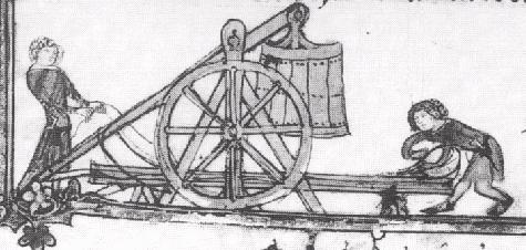
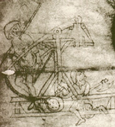
  1. The sling is long - you'll see a lot of this in other drawings..
  2. The sling appears to be held closed with a thin cord.
  3. The engine's crew get right in amongst the machinery.
  4. The archer beside the machine is being hit by a 'spear' - indicating that the siege engines were fairly close to the target, certainly within the range of the defender's fire. This enemy fire could be in the form of counter-bombardment by opposing trebuchets, heavy bolts from great crossbows or springaulds - or arrows from archers and crossbowmen.
    The impaled archer may have been speared by hand, but he may be intended to represent the victim of another war-engine, as elsewhere in the original is a representation of a great crossbow and its crew of Carlisle defenders.
  5. The crewman is holding a mallet, presumably to trigger the device.
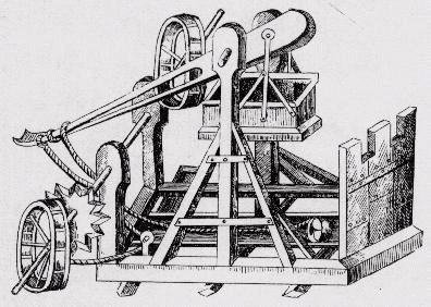
  6. The weight box has the suspension straps passing under it, rather than just taking the weight on the side timbers.
  7. There is also a not-entirely-clear structure drawn as if a part of the supporting uprights, forming an "inverted triangle" shape. This may be worth further investigation.

No doubt you will have noticed that this is the original from which the Grey Co Trebuchet title illustration is taken...


No. 2 - The Romance of Alexander

Trebuchet from The Romance of Alexander (circa 1330).
This picture is a little odd once you start measuring it - there isn't enough room for the weight to swing through the machinery. However, this is just a modern quibble, the details of the drawing show us quite a lot:
  1. Once again, the sling is drawn as being very long.
  2. A launch trough for the sling is clearly shown.
  3. A three-strap bucket suspension seems to be used. This one might be mounted inside the box.
  4. The winch is fitted with big wheels as handles - very practical. (or are these actually the sides of treadmills... more about these later)
  5. The winch is mounted on the main upright. In this drawing the weight would smash into it, but it is drawn as being high enough for the sling to pass under it easily.
  6. The winch rope is shown as being a loop draped over the beam.
  7. The crewman behind the machine is holding a rope which seems to do nothing. Is this representing something to do with the winch gear, or a trigger lanyard?
    .
 

No. 3 - "Bellifortis" (I)

A Trebuchet from "Bellifortis" by Konrad Kyeser von Eichstadt ( circa 1405) is seen here in a rather odd drawing with very wobbly perspective and quite possibly redrawn from an earlier publication.

Despite the inaccuracies of perspective we can see a number of useful features:
  1. The same 3-strap weight box suspension.
  2. Another very long sling.
  3. A winch at the rear of the engine, with its axle set high to avoid the sling.
  4. A ratchet? on the winch gear.
  5. Treadmills? similar in pattern to ones used on Medieval lifting gear (ie cranes) to power the winch.
  6. Protection for the crew and engine from enemy fire. (ie the machine is expected to be in enemy range.)

Just to illustrate my point about treadmill-powered medieval lifting gear, here are some pictures of similar machines.

One [on the right] is a moderately recent drawing of an early 15th century crane at Bruges, the other is a detail of a picture from "Die Biblie",1494. This style of treadmill-powered crane also appears in Roman carvings of the 1st Century AD)
Treadmill winches, far from being quaint and inefficient oddities, actually allow the crew to use their whole body weight to wind the gear.


No. 4 - "Bellifortis" (II)


Another trebuchet from Konrad Kyeser's "Bellifortis" (see above), this illustration is beautiful and detailed.
The drawing has it all:
  1. A weight box with three-part wooden suspensions which pass through the inside of the box and are attached directly to the bottom of it.
  2. A very long sling. The pouch of the sling appears to be held closed around the shot.
  3. A rear winch with the winch rope wrapped around it for only a few turns, rather than having all the rope gathered up on a winch drum. (This is a little like a modern yachting winch).
  4. There is a launch trough clearly shown, but it has a wall across the rear end. This implies that the sling is expected to have been lifted clear by this time, but the winch axle looks like it would be in the way. It's almost as if it has been drawn backwards...
  5. The axles supporting the beam and the weight-box suspension are drawn as if they are metal. (I've seen a coloured version of this picture... they're painted grey-blue)
  6. The beam, though not 'laminated', is re-enforced with metal straps.
  7. The side bracing beams are quite thin, apparently not expected to take much strain.
  8. All the other beams are very heavy, solid timber.
  9. The uprights look like they slope inwards, so that they are close together where they hold the main axle. This would minimise the length of the axle, but would require very skilled carpentry in building the frame.
  10. There is a rope passing over the beam that appears to terminate in a loop around the lower end of the loop-topped fitting that goes through the side base timber. This might well be the trigger mechanism. If the loop=topped pin is lifted the rope would be released.
The inward slope and the thinness of the side-bracing timbers are an interesting combination. With an inward sloping frame the side timbers would actually be in tension rather than compression and would be acting as "wooden cables".

 
- NAVIGATION -


Previous Next
Page
Main Page

Page
 

Russell Miners
This page was last edited Jan 2000