Medieval Mechanical Artillery
This page is dedicated to the reconstruction of projectile-throwing
siege engines.
The Visby Tr�buchet (1995)
This project was initiated by the committee of the campaign "R�dda Visby
Ringmur" ("Save the Ring-Wall of Visby") and financed with the help of
Cementa AB and the Municipality of Gotland. The reconstruction team, headed by Magnus
Sj�holm and Torgny Hederstedt (design & carpentry), included Patrik Djurfeldt
(additional design/historical adaptation), Anders Molin, Bj�rn Andersson, Fredrik
H�gglund (woodworking), Ingvar Hansson (ironwork) and Jan Gyllenborg (tackling). The
engine is now in the care of Gotlands Fornsal (the
County Museum of Gotland) and can be found outside the northern corner of the town wall.
The design is a simplification and development of that of an engine built in Denmark in
1989. Differences can be found in the joinery, the trigger mechanism, the addition of a
winch and a "counterweight propping beam", and a less complex tower and ground
frame structure. In addition, medieval woodworking methods and tools have been used as far
as possible.
The side frames, made of oak timber of 200x200 mm (8''x8'') cross section, supports the
axle at 3.5 m above the ground frame, also made of oak of 250x250mm (10''x10'') cross
section. With a total length of 8.6 m, the ash beam is divided in a ratio of 1:6, with a
short and long arm of 1.15 and 6.95 m respectively.
With a counterweight of c. 2650 kg (c. 5840 lbs., including timber weight), the
greatest range achieved so far is 193 m with an 11 kg lime stone. Standard ammunition
consists of concrete balls of 15 kg weight, with a range of c. 170 m. The beam can be
wound down by four men in 3-5 minutes.
Gallery
Click on the thumbnails to see the larger images or video.
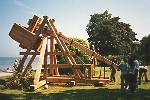 |
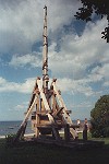
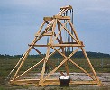
A side view of the newly finished tr�buchet (187kb). |
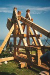 |
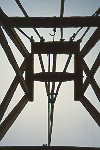
Note that the hole for the axle is below the centre-line of the arm. Two of the 15 kg
concrete projectiles can be seen on the ground (183kb). |
 |
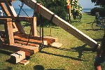
The sling rests empty on its slide trough. To reduce risks, all ropes used in
restraining the arm are left on until the launch (180kb). |
 |
The sling has been loaded with its projectile and pulled in under the arm. The double
winch rope with its hook is visible to the left. Next is a strong safety rope which is
secured the moment the arm has been wound down. In the centre of the picture the trigger
rope is visible with its loop attached to the trigger mechanism (240kb). |
 |
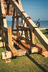
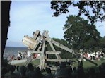
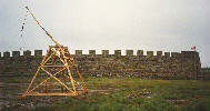
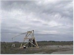
One year later, after having endured the winter by the sea without shelter, the
tr�buchet has turned grey. (This is not only a photographic effect!) Here, the
"propping beam" of the counterweight as well as its stop on the arm are clearly
visible. The winch handles have been temporarily removed to prevent unauthorized use of
the engine (155kb). |
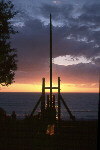 |
Sunset in August 1998 (52kb). Photo � Kenneth Eriksson |
 |
Video(mpeg):
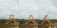
The slow and powerful motion of a large tr�buchet is very different from the violent
action of a torsion engine. In this case, the arm has not been wound down quite as far as
it should have been, because of a stretched trigger rope (1007kb). |
 |
Video(mpeg):
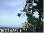
This shot shows one of the hazards of operating a tr�buchet. After the release of the
stone the sling continues along its arc and the end of the sling rope swings down at great
speed. Note how the heads in the crowd turn to follow the stone in the air (916kb). |
The Eketorp Traction Lever Engine (1998)
A full-scale traction lever engine was built 22-26 June 1998 at the reconstructed
fortification at Eketorp, on the island of �land
in Sweden. The reconstruction team consisted of Patrik Djurfeldt (historical research
& design), Magnus Sj�holm and Torgny Hederstedt (carpentry & additional design),
and Jan Gyllenborg (tackling). Medieval woodworking methods were used as far as possible.
The engine is of a fixed direction type with tetragonal supporting structure. It is
designed for a traction crew of 6-20 men standing inside the framework. If the engine is
covered with boards on the front and sides, the crew is protected from missiles.
The arm, made of ash, is 4.94 m long and is divided by the axle into a long and short
section of 4.11 and 0.83 m respectively. Attached to the tip of the arm is a 1.5 m long
sling with a leather pouch. The axle is supported at 3.6 m above the ground by two oak
frames, with main beams of about 100x100 mm (4"x4") cross-section.
Normally, an engine of this size would have had a flexible arm. Although it was
initially the intention to provide the engine with such an arm, practical considerations
made it necessary to use an arm of such cross-section and dryness that a "stiff
arm" launch technique had to be adopted.
After the first two days of not very intensive testing the longest range achieved was
c. 145 m with a stone of 1-1.5 kg weight and a traction crew of 6 men. The longest range
achieved so far is estimated to 185-190 m (the stone was found at a distance of 191 m, but
the exact point of impact was not identified) with a light stone of below 1 kg and a crew
of 6 men. The engine has not yet been properly adjusted for maximum range. In the summer
it is fired every day at 12.00.
Gallery
Click on the thumbnails to see the larger images or video.
 |
(135 kb) |
 |
A view from the inside of the engine looking up towards the axle from the location of
the traction crew. Here, the throwing arm is pointing forwards (127 kb). |
 |
A launch with a 6 man traction crew in 2 rows (41kb). |
 |
Two reconstructions (182kb). |
 |
Video(mpeg):
A shot fired during the second day of testing. The launch technique used here was found to
be the best for the rather stiff arm of this engine (728kb). |
The Author's Own Tr�buchet (1997-2000)
When I began my thesis work on the dynamic behaviour of counterweight lever artillery,
it soon became obvious that it would be necessary to have an engine close at hand to
verify theoretical results. Furthermore, it would be necessary to have unrestricted access
to the engine as well as a permission to modify it at will. The only solution was, of
course, to build one especially for that purpose. Although it would have been desirable to
build a large engine, my limited resources would not allow it. I had to settle with a
smaller one, with a counterweight of about 500 kg.
Gallery
Click on the thumbnails to see the larger images.
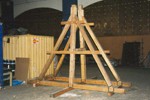
 |
(68kb) |
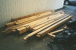
 |
The engine under construction (66kb). |
 |
The wheels of the wooden winch (76kb). |
 Main Page
� 1997 Patrik Djurfeldt
This page was last updated
2004-06-26


